ETC controllers are equipped with one or more digital outputs. These digital outputs can be turned on and off to signal to other systems, provide power to external devices, or run relays to turn higher power devices on and off.
Physical Connections
The default purpose of the digital outputs is to provide power to external pressure sensors, such as line pressure and casing pressure transducers. The PWR connection can be turned ON (5 V) or OFF (0 V) at different times depending on what a given output has been configured to do.
Digital Output 1
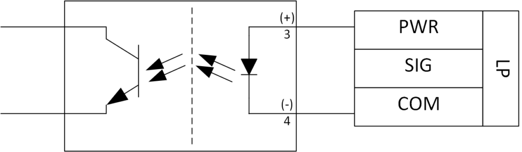
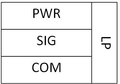
This is available on all models of controller. It is typically labelled as LP – PWR as it is intended to be used for line pressure. Configuration is available in the Outputs menu.
Digital Output 2
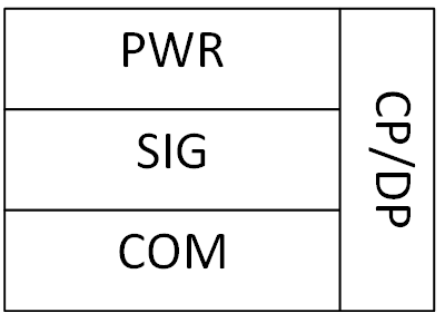
This is only available on the more advanced models of controller. It is typically labelled as CP/DP – PWR as it is intended to power pressure optimization devices such as casing pressure or differential pressure transducers.
Output Configurations
Each digital output can be configured independently through the outputs menu. The available selections vary based on the valves and devices that are enabled. The number of digital outputs also varies with the model of controller.
Default
All digital outputs are setup by default to provide power to a connected pressure transducer. Voltage will not appear on the PWR pin for a given device unless the device is enabled and it is being sampled. For most pressure devices, the power is only turned on for a fraction of a second each second, so it cannot be measured with a standard meter. Only an oscilloscope would see the pulse on this connection.
Mimic Valve
The digital outputs can mimic any valve that is enabled on the controller. If there is a valve, such as an auto catch that you would like to mimic that is not available; first ensure that the auto catch is enabled.
Level
By default, the output is turned ON (5 V) when a given valve is opened. The output is turned OFF (0 V) as soon as the valve is closed. This is useful when connecting to a relay. The relay is energized when the valve is open, allowing devices such as en electric valve to be powered. When the valve is closed, the power to the relay is removed, cutting power to the electric valve.

Pulse
Alternatively, the output can be set to pulse. In this instance, we can set the output to pulse on open or pulse on close. When the desired valve operation occurs, the output is turned ON (5 V) for a specified amount of time (in milliseconds). After this time has lapsed, the output is turned OFF (0V).

This is useful for communicating with interfaces that require a short duration pulse instead of level that is held until the valve state changes. One example is the Kimray Electro Hydraulic Valve. This valve requires 2 signals, one which pulses when the valve is expected to open and another that is expected to pulse when the valve is closed.
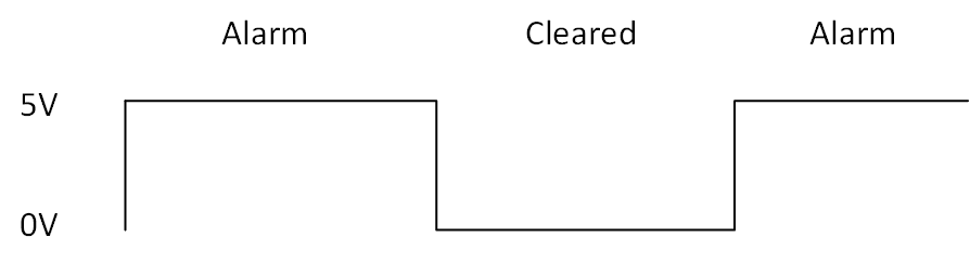
On Alarm
This feature is used to communicate with other systems when the controller has gone into an alarm state. If the controller stops operating because it has a low battery or another alarm condition has caused the internal state machine to shut the well in, the output will be turned ON (5 V). When the alarm condition is cleared and normal operation resumes, the output will be turned OFF (0 V).
Recommended Interface Devices
Optically Isolated Relay
An optically isolated relay separates two different systems so that there is no electrical path between them. ETC controllers are connected to the low power side of the relay. When the PWR connection is turned on, the relay allows current to flow between the other set of connections.